Commodore Amiga Retro
![]()
Please remember that text for pages was originally
written for my Amiga 1200 to read... so thin paragraphs
Amiga Workbench
Help with the A4000 Memory Simms
AMIGA A4000 RAM
Fast RAM Banks and SIMM size:
The four Fast RAM sockets are labeled on the
motherboard as Banks 0,1,2 and 3, and they must
be filled in that order. If your Amiga has one
or more banks occupied , place additional SIMMs
in the next higher numbered banks.
The Fast RAM SIMMs can be one of two memory sizes
one megabyte ( 1 MB ) or four ( 4 MB ). By filling
the indicated banks with the appropriate size
SIMMs, the following Fast RAM configuration is
possible.
Amount of Fast RAM - SIMM Size - Banks Filled
1 Megabyte - 1 MB - 0
2 Megabytes - 1 MB - 0,1
3 Megabytes - 1 MB - 0,1,2
4 Megabytes - 1 MB - 0,1,2,3
4 Megabytes - 4 MB - 0
8 Megabytes - 4 MB - 0,1
12 Megabytes - 4 MB - 0,1,2
16 Megabytes - 4 MB - 0,1,2,3
Note that the two sizes cannot be mixed within the
Fast RAM section. The physical packaging of the
Fast RAM SIMMs must be single-sided, 1 inch /2.54 cm
or less in height.
Jumper Settings:
J852:1-2 Closed RAM Size 1 Mb x 32
J852:2-3 Closed RAM Size 256 KB x 32
FAST RAM:
1 MB SIMM = 256K x 32/36
4 MB SIMM = 1 M x 32/36
Total Fast RAM ADDRESS SIMM Config
1 Megabytes - 07F00000-07FFFFFF - One 1 MB SIMM
2 Megabytes - 07E00000-07FFFFFF - Two 1 MB SIMMs
3 Megabytes - 07D00000-07FFFFFF - Three 1 Mb SIMMs
4 Megabytes - 07C00000-07FFFFFF - Four 1 MB SIMMs
8 Megabytes - 07800000-07FFFFFF - Two 4 MB SIMMs
12 Megabytes - 07400000-07FFFFFF - Three 4 MB SIMMs
16 Megabytes - 07000000-07FFFFFF - Four 4 MB SIMMs
Fast RAM
Up to 16 Megabytes
Four 72-pin SIMM sockets
32-bit CPU interface
Page or Static Column mode
80 ns
The SIMMs are 72-pin JEDEC standard. Many 72-pin
SIMMs are 36 nits wide. This machine requires only
32 bits of data. If a 36-bit SIMM is used, then the
extra 4 bits are simply ignored.
Fast RAM is controlled by the same RAMSEY chip used
in the A3000. RAMSEY was designed to terminate
cycles via *STERM. Since the 68020 only has *DSACKs,
external logic is required to provide *DSACKs to the
CPU in a synchronous fashion.
Burst mode is still functional for Fast RAM , but the
68020 does not have this capability. If a 68030 is
installed in the coprocessor slot , it is desirable
to have this turned on. Therefore, the test for static
column DRAMs should be left in the ROM, and the BURST
bit turned on just as is done with the A3000. However,
the test for static column DRAMs must be done differently.
Instead of writing four longwords with the static column
bit set , and then reading them back with it off, the
four longwords should be written with the bit set off, and
then read back with it turned on. This is necessary because
JEDEC standard SIMMs do not make use of an output enable
(*OE) pin for the DRAMs. When static column mode is
turned on, all writed to the DRAM are done as late writes.
Without the *OE pin, the SIMMs cannot do late writes.
The test will fail indicating the correct result, but
more significantly the data being written to the DRAMs
will collide with data coming out of them, which is
undesirable. Static column SIMMs must be custom made.
One of the no connect pins will be assigned to act as the
*OE pin. Only after it is determined that the DRAMs are
the static column type should a write to DRAM in static
column mode ever be allowed.
The test described above for static column DRAMs should
not be done with a 68020. The software should check that
the processor is a 68030 or 68040 before doing this test.
Since the 68020 uses DSACK, this test will not perform
properly.
If static column DRAMs are installed, page mode operation
is functional as well ( when the bit is turned on ).
CHIP RAM:
Up to 2 MB via one 72-pin SIMM
32-bit CPU interface
32/16-bit Chip interface
Page or Static Column mode
80 ns
The base machine will contain 1 MB of Chip RAM and is
expandable up to 2 MB on the motherboard. The first
1 MB resides on the Chip RAM SIMM, configured as 256K
x 32. If 2 megabytes of Chip RAM is desired, then this
SIMM must be replaced with a single 512K x 32 SIMM.
The 2 MB of Chip RAM appears at 0000000-01FFFFF. Any
uninstalled Chip RAM in this 2 MB will read back as
`Garbage`
Total Chip RAM - Configuration
1 Megabyte - One 256K x 32/36 SIMM
2 Megabyte - One 512K x 32/36 SIMM
SYSTEM START-UP
The system startup sequence consists of series of
tests than run automatically whenever you turn on
the computer. This test series resides permanently
in the BIOS. It performs CPU and keyboard tests to
verify basic system operations.
If the system finds an error before the screen display
turns on, the screen will remain blank and the system
halts. After the screen display turns on, the screen
changes color and the system haltsif an error occurs.
The screen color helps you identify the type of system
problem. The screen colors represent:
Passed Test - Light Grey - Initial hardware tests passed
Initial system software tests passed. Final initialization
test passed.
Failed Test - Red - ROm Error - Reseat or replace
Green - Chip RAM error ( reset Agnus retest )
Blue - Custom Chip(s) error
Yellow - 68000 detected error before software
trapped it ( GURU )
The system performs the following test sequences:
1. Delays beginning the tests a fraction of a second
to allow the hardware to stabilize.
2. Jumps to ROM code diagnostic card ( if found )
3. Disables and clears all DMA and interupts
4. Turns on the screen.
5. Checks the general hardware configuration.
If the screen remains light gray color and the tests
continue , the hardware is OK.
If an error occurs, the system halts.
6. Performs checksum test on ROMs
If the system fails the ROM test, the screen display
turns red and the system halts.
7. Begins the system startup sequence
8. Sets up temporary exception processing.
If a processor error occurs, the screen display turns
yellow and the system halts.
9. Tests the Chip RAM
If memory configuration error occurs, the screen display
turns green and the sytem halts.
10. Tests Custom IC register addresses
If address error occurs , the screen display turns
blue and the system halts.
11. Checks to see if the system software is operating
properly.
12. Restores the screen.
MEMORY TEST: MBRTest-2 Utility.
A4000 User`s Guide - 400424-01
International Edition - containing
part number information which may vary.
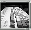
If you can only see this CONTENT window
then click the image above for the full site
Last updated 07/10/06