Commodore Amiga Retro
![]()
IDEFIX Help
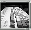
GENERAL: A typical buffered interface has PIN 1 to the left hand side with
Channel 2 upermost (40 way), then Channel 1 (40 way) Channel 1 (44 way) and
then at the bottom the connector to the Amiga 1200....

They usually consist of two small (44 way) and two large (40 way) IDE connectors.
They can usually support upto 4 devices with the necessary software.

When installing an interface, or trying to eliminate problem, the best solution
is to connect the devices up in stages:

(1)Ensure that your computer will boot up with your original hard drive
connected. N.B. A good tip to reduce the amount of time waiting for the
system to boot is to hold both mouse buttons buttons down when you first
switch on. Providing you can see the early Boot Options screen, then the
computer is usually OK.

Please also ensure that all necessary precautions are taken when working
on an open Tower or computer. Needless to say, these notes are provided
to assist you in fitting your equipment and no responsibility is taken
for any damage to either yourself or your computer.

(2)Now you need to connect a 44-way IDE cable from the computer to the
buffered interface. Most if not all , cables have a single coloured wire
which is normally used to connect to and identify Pin 1. Pin 1 on the
A1200 motherboard is clearly marked, but for clarification it is the
side of the connector closest to the front of the motherboard (PCMCIA port).

(3)Then connect the other end of the 44-way cable to the buffered interface.
The connector on the interface labelled normally to the A1200 is the bottom
most connector. You must ensure that Pin 1 on the interface is connected to
Pin 1 on the motherboard . Since the 2.5"(44-way) IDE interface carries the
power as well as data signals you can damage both the interface and the
cables by connecting the cable incorrectly. Care should also be taken to
ensure that when connecting the 44-way IDE cable onto either the motherboard
or interface that you do not miss any of the gold pins. It is very easy to
miss a pair of pins at one end of the connector, or miss a whole row of 22
pins completely. Again damage may sometimes occur when connecting a cable
incorrectly. You could at this point try to switch the computer on. Having
just a cable and interface connected will not affect the operation of your
A1200.

- You should still be able to get the early boot screen.

(4) The next stage is to connect your hard drive. In order to boot from a
HD attached to your interface it must be connected to Channel 1, sometimes
called the  Primary Port or Channel. If you are using a 3.5" HD it must be
set as Master. There are jumpers to configure the drive and usually instructions
or a diagram on the drive to show you how to do this. The drive should
be connected to Channel 1, 40-way IDE connector.

If you have a 2.5" hard drive then it will most likely be set to Master or
only work as Master. This should be connected to Channel 1, 44-way IDE
connector. You may intend to have another device also connected to Channel 1
on the same cable but it is usually better in the long run to test the system
at this point before adding any more devices.

(5)Once the system is working you can then continue and add more devices again
testing, and installing software where necessary, each time before adding the
next.

General Notes/Tips:

If you connect a ribbon cable incorrectly it will usually damage the interface
cable itself. It is therefore usually a good idea to test, where possible with
the system open so you can see any damage as early as possible.

A good tip is to watch the power LED on your A1200 or tower. A working system
will provide an early indication of the operation through the LED. The correct
signal should be :- When you first switch on, the LED should be lit dim,
then after a moment  the LED should become bright. ( Note with a PPC fitted
it may take several seconds before this happens ). If this happens then you
have most likely connected everything correctly and will be able to verify
this by checking the Early Boot screen.

If the LED remains dim then the last item connected or added is preventing
the computer from operating - check the connections. If the LED flashes dim
and bright then again check your last connections. If the LED does not light
first dim then bright in the normal time ( approx 2 to 3 seconds ) then
switch your system off immediately. Cables can and do melt if connected
incorrectly and the sooner you switch of the better  your chances of preventing
permanent damage.

The orientation of Pin 1 on the most if not all drives should be the same. On
HDs and CD ROMs Pin 1 is on the right hand side when you look at the rear of
the drive.

If you intend using Channel 2 to connect a HD or removeable media drive
(LS120/ZIP) then you will need to install EZ-IDE/IDEFIX. To add a HD using
Channel 2 you will also need to add C:IDEFIX to your startup-sequence just
after the C:SETPATCH line. You can use an editor or open a CLI/SHELL and
type "ed s:startup-sequence" and press enter. N.B. do not type the inverted
commas.

Then add the C:IDEFIX line on the line below C:SETPATCH, and save changes
and exit. You will need to reboot your computer for the changes to be
recognised. This alone will not allow you usually to recognise the HD.
You must also run HDTOOLBOX, normally on your INSTALL disk or most magazine
cover CD's and select save changes to drive. The program should tell you
that drives have been added or removed and that you need to do this! You
may at this point need to ensure that the maxtransfer setting is correct.
Incorrect settings can result in corrupt or lost data during data transfer.
The recommended setting is 0xFE00. This setting can be changed by clicking
on advanced in the partition section of HDTOOLBOX. Please note that you will
to press ENTER before you click OK, otherwise the program does not recognise
the new value. This setting must be set for ALL the partitions on your drive.
When you have done this a re-boot may be necessary. Once this has been done
WB should recognise the new drive. It may recognise the partition as DH0:ndos
or HD0:???. This is usually a sign that the drive has not been formatted.
You can normally just carry out a quick format using the WB format menu.
DO NOT DO A LOW LEVEL FORMAT as suggested in HDTOOLBOX - This can damage
the drive !!!

To correctly install and use an LS120 or ZIP drive you must first connect
the hardware and then run the INSTALL LS120 program. This is usually
installed within your IDEFIX97 drawer on your HD. You use the same installer
for both LS120 and ZIP drives. During the installation process it will open
the FindDevice program and should correctly identify the device. You may
need to select ATAPI.DEVICE and then click use. When the installer has finshed
it should have added a new line to your user-startup and mount the drive.
You will need to reboot. When you have rebooted put a disk/cartridge in
the drive. You may get two icons appearing PC4 and DF4 - there are two
dosdrivers to allow the reading of AMIGA or PC disks. You can prepare
either type by doing a QUICK format on the appropriate icon.

Some new UDMA CDs need to be set as Master in order to get the best performance.

Some CDs also hang the system when used on their own with C:IDEFIX in the
startup-sequence. If you use the drive as a slave to another then they
usually work fine. If the drive is on its own then you do not need the
C:IDEFIX command in the startup. Simply put a ; in front of the line
eg ;C:IDEFIX - This will instruct the system to ignore it. When you
require the command (recognise a HD ) then just delete the ;

Usually the preferred configurations for HDs and CDs are as follows:

----------------------

1 x HD and CDROM

Channel 1 Master Hard Drive

		Slave

Channel 2 Master CDROM

----------------------

1 x 2.5" HD, 1 x 3.5" HD and CDROM

Channel 1 Master 2.5" Hard Drive

		Slave 3.5" Hard Drive

Channel 2 Master CDROM

		Slave

Note: If your system will not work with a 2.5" Drive
with a 3.5" Slave you may have to set up as below.

----------------------

1 x 2.5" HD, 1 x 3.5" HD and CDROM

Channel 1 Master 2.5" Hard Drive

		Slave

Channel 2 Master 3.5" Hard Drive

		Slave CDROM

EZ-IDE/IDEFIX Required

----------------------

2 x 3.5" HD and CDROM

Channel 1 Master Hard Drive

		Slave Hard Drive

Channel 2 Master CDROM

		Slave

OR

----------------------

2 x 3.5" HD and CDROM

Channel 1 Master Hard Drive

		Slave

Channel 2 Master Hard Drive

		Slave CDROM

EZ-IDE/IDEFIX Required

----------------------

1 x 3.5" HD , 1 x LS120/ZIP and CDROM

Channel 1 Master Hard Drive

		Slave

Channel 2 Master LS120/ZIP

		Slave CDROM

EZ-IDE/IDEFIX Required

----------------------

Quick Installation Guide for CDROM Drives

1: If you have one Hard Disk make sure it is connected to either Port 0
connectors. [ Channel 1 ]

2: Connect the CDROM drive to OUT PORT 1 (Channel 2:  Make sure the CDROM is set to
slave )Make sure the IDE cables are plugged in the right way ( The red wire
on the IDE cables all match Pin 1 )

3: Make sure CDROM is switched on. Let Workbench load up and insert IDEFIX
disk. Run the install icon.

4: Select "proceed" and "yes" for all options.

5: When the "find device" program is run, click on the atapi.device on the
left hand side window.

6: The name of your CDROM should appear on the right hand side window. Select
the CDROM and click "use" and carry on with the installation.

7: Once installation is complete then reset the computer . Insert a CD and
an icon should appear on your Workbench.


For more information look at the documentation in the docs drawer on the
IDEFIX disk.
If you can only see this CONTENT window
Last updated 22:36 15/04/2010 |